Spray Gun Motion Study

In finishing any component the most efficient combination of spray gun movements must be carefully planned in order to produce the best results. At the same time the parameters within which the gun operates best must also be considered. The following notes are intended to highlight the best way to use the gun. Before commencing spraying it is advisable that an operator becomes familiar with the gun and surface to be coated by spraying some practice panels to save time and rejects during later production.
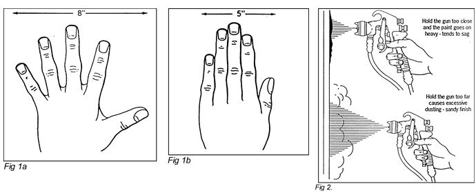
The Stroke (Pass)
The spray gun stroke, or pass, is made by moving the gun parallel to the work and perpendicular (at right angles) to the surface. The distance from the gun to the work, for Conventional Air Atomising guns, should normally be between 6 and 8 inches. A simple way to measure this to use your hand. A closed hand (with fingers and thumb together) measures approximately 5 inches wide and an open hand (with fingers and thumb apart) measures approximately 8 inches (as shown in figures 1a and 1b).
Spraying should be carried out with straight uniform strokes moving across the surface in such a way that the spray pattern overlaps the previous stroke by a minimum of 50%.
While this percentage may need to be increased for certain coating types, once established, it must remain constant for the duration of the work. Failure to do so will result in uneven coating thickness and poor visual appearance. If the gun is held too close to the work surface, more paint will be deposited and the gun will need to be moved faster to prevent runs and sags and possible solvent entrapment.
Likewise, if the gun is held too far from the work, the atomised droplets may dry completely before coming into contact with the work surface, causing excessive spray dust and dry spray, (as shown in Figure 2).The relation between the gun distance and the stroke speed is easier to see when actually spraying. The sprayer will soon become experienced in moving the gun target distance closer or further away to permit a comfortable speed, while depositing a full wet coating of material. Remember at all times that the Conventional Air Atomising gun is designed to spray at 6 – 8” inches and deviation from this distance by altering fluid flows and air pressures is not good practice. It could lead to other paint defect problems.

The gun must not be excessively arced or tilted while spraying, as shown in Figures 3 and 4. In certain types of work it is necessary to tilt the gun but this should only be done when it is not possible to use the correct gun position.
Holding the Gun
The gun must be held at right angles to the sprayed surface at all times. Figure 4 shows the correct position in which the gun should be held, and also the incorrect in dotted lines. It is especially important to remember this when spraying particularly
low or high surfaces where holding the gun at right angles takes more effort on the part of the sprayer. Failure to do this will result in heavy and light bands of material caused by the deformed spray pattern shape brought about by the incorrect angle of the gun.
Triggering
The gun trigger controls the quantity of material emitted from the fluid tip, and the operator needs to learn how to correctly use it to achieve the most efficient spraying technique. As the trigger is pulled back the flow of material increases. Continuous adjustment of the fluid flow is normally necessary when spraying complicated or intricate components. It is therefore important to become familiar to the trigger ‘feel’ to prevent deposition of too much coating on certain areas of the component. Correct use of the trigger will also reduce the amount of paint wasted and contamination in the spray area.
Spraying a Panel
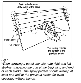
The basic technique of spraying a flat panel is shown in Figure 5. The stroke is started off the work and the trigger is pulled only when the gun is moving and about to pass over the edge of the panel. The trigger is released at the other edge of the panel but the stroke is continued a few inches before reversing direction for the second pass. The point at which the gun is triggered is one of the most important factors of the spray technique. The gun must follow the precise shape of the work, maintaining full coverage over the wok with minimum waste in overspray.
In order to reduce overspray and waste some sprayers use an ‘end stoke’ technique as shown in Figure 6. The first single vertical stroke at each end of the panel allows the gun to be triggered off just before the panel edge. This method still assures complete coverage but helps reduce paint waste which results when spraying up to and over the vertical edge with the usual horizontal strokes.
Long work
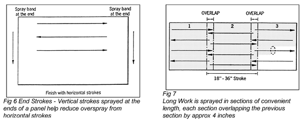
A long panel can be sprayed with vertical strokes, but most sprayers have better control with the more natural horizontal stroke. The panel should therefore be sprayed in several separate sections typically 18 to 36 inches long (a comfortable reach of the sprayers gun arm) as shown in Figure 7. This method will use the same triggering action as with a smaller panel, but each section must overlap the previous one by about four inches. By ‘feathering’ the gun trigger and slightly ‘arcing’ the gun for this four inches, heavy material deposition from two full coats can be avoided. Do not attempt to spray the complete panel length in one pass – this will easily lead to overlap and target distance errors.
Horizontal Surfaces
When spraying horizontal surfaces one option is for the spray strokes to start at the near side of the work as shown in Figure 8.
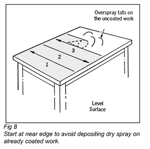
This is essential where rapidly drying materials (e.g. cellulose lacquer) are used, as drying droplets from the bounce-back landing on wet work can dry with a sandy finish. A very small amount of gun tilt is usually needed for horizontal surfaces to ‘sweep’ the bounce-back toward the far edge. The newly deposited wet coat will tend to bury any dry spray already deposited on the surface.
The opposite action is also acceptable (i.e. starting at the far side and ‘sweeping’ towards the sprayers body. However, the sprayer himself will become covered in dry spray.
When spraying horizontal surfaces too wide to be coated from a single side it is common to start at the near side and spray towards the middle using the ‘sweeping’ technique described above. On reaching the middle the sprayer will move around to the far side and spray from the middle to the new near edge, again ‘sweeping’ the dryspray, but this time towards the sprayers body.
This latter technique is typically used when spraying the roof and bonnet of cars, as it has the advantage of keeping the ‘wet edge’, allowing wet paint deposited by spray strokes to merge into that deposited by the previous stroke across the complete surface width. However, care must be taken not to allow the sprayer or the gun hose to touch the wet surface while spraying.
Tilting the Gun
Where a suction feed spray gun is used on work that requires the gun to be tilted, care must be taken to ensure that the tilt is not excessive as the paint may clog the air vent in the cup lid and interfere with material flow. As an alternative the air cap can be rotated to keep the gun and cup vertical while the spray fan is angled.
If spraying at an upward angle for any length of time one option is to rotate the complete cup assembly through 180 degrees so that the air vent lies in front of the fluid inlet, and the fluid tube, within the cup, curves to where the material will lie when the gun is tilted. An even better idea is to use a pressure feed system.
Outside Edges and Corners
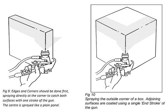
When a panel is to be sprayed on the edges as well as on its faces a modified End Stroke technique is used as shown in Figure 9. One stroke along each edge coats part of the faces as well as the edges at the same time.
An outside corner of a box or cabinet is treated in a similar manner, as shown in Figure 10.
Inside Corners
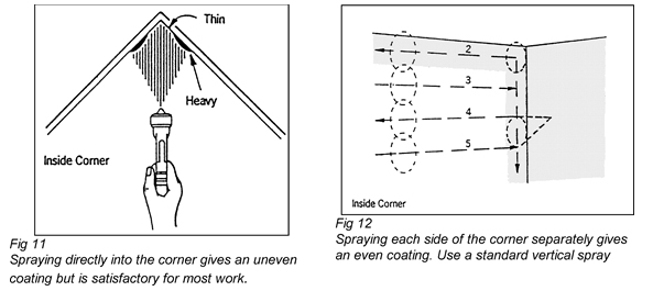
If an inside corner is sprayed square-on, as shown in Figure 11, the coating will not be truly uniform but it will be applied quickly and will be satisfactory for most work. To overcome ‘Air Cage’ produced by air atomising guns it is normal for the gun, and therefore the spray fan, to be inclined at a slight angle to increase penetration and coverage.
When a more even coating is necessary, each face of the corner is sprayed separately as shown in Figure 12. After making the first vertical stroke next to the corner, horizontal strokes can then be used to cover the area adjacent in order to avoid overspraying or double coating the adjoining surface.
Slender Work
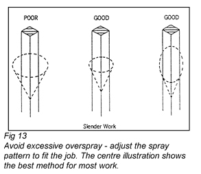
When spraying slender work the spray pattern must be adjusted to suit the components being sprayed. A wide horizontal spray pattern must not be used on a narrow work. A smaller horizontal pattern or (sometimes) a large vertical fan spray gives complete coverage without excessive overspray. However the use of a spray pattern that is too small for the component must also be avoided or banding and uneven material deposition could occur.
Jetting
Occasionally the smallest size fan or round spray is used to concentrate paint and air flows in order to ‘throw’ or ‘jet’ the material over increased target distances. Although increased orange peel will normally result this method is useful for coating awkward areas that are inaccessible or beyond normal spraying reach.
Open Work
Iron grilles, fences and similar work should be sprayed with the intent to get the material on the largest area with each stroke of the gun.
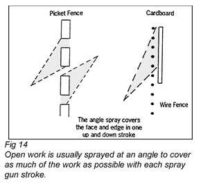
A picket fence can be sprayed with a single up-down angle stroke on each side. A wire fence or other thin, intricate, work should also be sprayed at an acute angle as shown in Figure 14. It is helpful to use a shield behind the wire as paint deflected by bounce-back will help to coat the back of the work.
The idea of using paint deflected by bounce-back to coat difficult areas of components is often used during production spraying. However, it must be realised that the deflected paint droplets will have evaporated much of their solvent content before finally landing and therefore a orange peel finish is often obtained.
Round work
A flat round disc is sprayed like any other plane surface, spraying the edge as shown in Figure 6, and then spraying the centre.
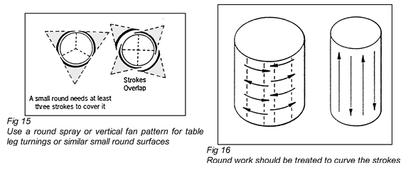
Small, cylindrical shapes such as table leg turnings are ideally sprayed with a round spray pattern, vertical stroke, using three or four lapping strokes to obtain full coverage, as shown in Figure 15. A vertical fan pattern can be used in conjunction with the vertical stroke, but the movement of the gun must be increased to prevent runs or sags.
Large diameter cylinders are usually finished in the same manner as a flat panel except that the strokes are shorter, as shown in Figure 16. A small diameter cylinder is more efficiently sprayed with lengthways strokes as shown in Figure 16.
Continuous Spray Motion
An important element that has been found to greatly increase the efficiency of spraying operations is the principle of keeping continuity of motion, from the time the gun is triggered when starting to spray, until the gun is triggered off and the component is completely covered.
This does not necessarily mean that the entire article should be sprayed without shutting off the gun, however when possible this should be done.
Mounting certain types of work on a turntable which can be revolved easily can allow an object to be sprayed with one or two simple motions without shutting off the spray gun more than once or twice.
Such continuous, or nearly continuous, operation of the gun will assure maximum coverage per unit of time and so will produce a maximum output from the spraying operation.
In such work, it is usually necessary to provide a turntable with mounting jig to hold the object securely during painting so that it may be rapidly positioned for complete access to all portions. Then, by working out sequence of motions for the spray gun, complete coverage of the component can be attained with a few rapid strokes and simultaneous, or alternate, movements of the fixture holding the work.
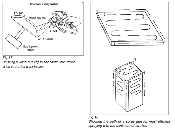
Figures 17 and 18 show some typical examples of the recommended practice in spray gun motion and show how a component can, in many cases, be efficiently covered by one or more continuous strokes of the gun.
Where the object to be sprayed is of such a shape that it can be rotated while it is sprayed, the gun can be held open from beginning to end of the stroke. Figure 17 shows a method used in spraying metal hub caps of wheels. The work is held and rotated by the turntable. A 5 inch spray pattern is used. As the hub rotates the operator simply pulls the trigger back and moves the gun in a 2 inch arc, finishing the cap in one continuous operation.
It is not necessary to zigzag this stroke or move from top to bottom and back again. In the example shown the top half of the hub cap is finished on the first revolution, and the second half by slight movement of the spray gun. The width of the spray pattern must be adjusted to suit the area to be covered.
Figure 18 shows how continuity of motion can be worked out for a flat surface such as a table top.
Figure 18 also shows a diagram of how continuity of motion may be planned for solid objects such as cabinets, metal covers, cases, etc. In both cases the spray gun is triggered to feather out the strokes.
In any motion study for spray guns it is desirable to determine the fewest number of strokes and least amount of motion necessary to obtain the desired coverage. Therefore, the design and use of suitable fixtures will be found a great aid.
Modifications to Technique
While the above techniques and procedures were written with Conventional Air Atomising spray guns in mind, they are all generally applicable to most other types of spray equipment as well. However, due to different fluid emission rates and atomisation methods there will be some differences as listed below:
HVLP
Generally, slightly decreased target distances (7 to 8 inches) will be necessary to counter the slower paint droplet speed and the higher solvent evaporation rate caused by the higher volumes of compressed air used by these guns. It should not be necessary to slow down pass speed and only in extreme cases will solvent types need to change. Jetting distance will normally be less than for Conventional Air Atomising guns.
Airless
Target distance will depend upon the tip size and fluid flow used, although 8 to 12 inches is normally recommended. Successfully because of low droplet speed and lack of adjustment of fan size on the gun. Pass speed will need to be increased due to the increased fluid flow rates. Triggering is essential.
Airless Air Assisted
Similar to airless, although fluid flow rates will be marginally less and target distances similar to Air Atomising guns are recommended. Triggering is again essential.
Conventional Air Atomised Electrostatic
As per non electrostatic air atomising although target distance may need to slightly increase to get the best from the electrostatic ‘wrap-round’ effect shown in Figure 19.
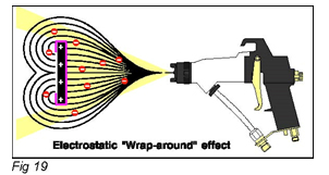
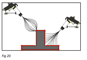
Due to this and an increased evaporation rate caused by the electrostatic effect, solvent types may need to be altered to slightly slower blends. Faraday Cage effect will give difficulty when trying to coat shielded areas such as corners (Figure 20) where paint will be drawn toward the closest grounded object. For the same reason components that are too close together will tend to ‘rob’ paint from other areas. Care must be taken to avoid build-up of paint on sharp edges and corners for the same reasons. To help overcome this problem it may be necessary to reduce or turn off the electrostatic power and use the gun like its non-electrostatic counterpart.
Airless Air Assist Electrostatic
As per non electrostatic airless air assist although target distance may need to slightly alter to get the best from the electrostatic ‘wrap-round’ effect. Increased evaporation rate will be worse due to the addition of electrostatics to the airless atomisation method. Faraday cage will be worse than Air Atomised equipment due to lower paint droplet velocity, although wrap-around will also be increased.
Airless Electrostatic
As per non electrostatic airless although target distance may need to slightly alter to get the best from the electrostatic ‘wrap-round’ effect. Increased evaporation rate will be worse due to the addition of electrostatics to the atomisation method. Faraday cage will be worse than Air Assisted Airless equipment due to lower paint droplet velocity, although wrap-around will also be increased.
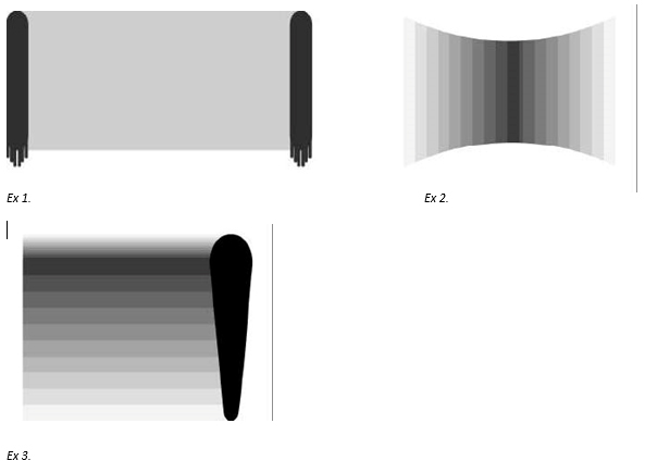
Although only shown in diagrammatic form what types of bad spraying technique do you think caused the following bad spray patterns and material deposition?
Source: Finishing Brands.
